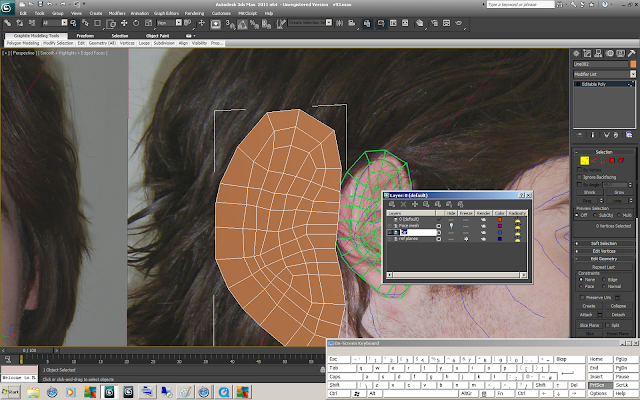
Return to photoshop and repeat reference plane method for ear
This can be done in the same file
Save file - return to max
If file has not automatically updated there are two easy options
1. Add new bitmap with updated file - change material link to new bitmap
2. Go into bitmap settings - reload
Reference planes should appear as previously however with new guidelines
Hide head via layers menu
Repeat previous process to create geometry mesh of ear
Open layers menu - create new ear layer for geometry
Make ear see through - hotkey alt + x - add turbosmooth modifier - begin to create shape - add depth
Used connect to create geometry then pushed it into ear to create overlap of ear
Highlighted geometry - inset - extrude
This geometry is the moved and shaped as required
Result with turbosmooth on (Can help to edit in this view ie simple mesh over detail model using final result tool on modifier stack
Ear cavity is extruded as necessary
Added more geometry to inner ear
View with turbosmooth
Start to wrap geometry round back of ear using shift + edge drag (scale tool)
Move points inwards (make sure not to overlap geometry) - create second set of geometry protruding backwards (excessive detail not required as back of ear will not be visible
Ear rotated now created to align with reference planes
changed head colour for easier blog visulisation
Make head visible via layers menu
Hide ear via layers menu
Highlight and remove polygons for ear to be attached (use reference planes if necessary to see which polygons lie within ear placement)
Show ear via layers
Remove / add any geometry to hole as necessary
Align ear geometry to head geometry best as possible (removed extra sections on head to accomidate extra ear geometry - this decision was later reversed)
Group extra geometry together to tessalate ie for every one point group 2 points to be tessalated into one
Tessalate geometry whether possible to create same amount as head for target welding (if there is too much geometry - in this example there is)
Attach ear to head and target weld to connect geometry
[In this example found that head was attached to ear. This was an error and has effect heirachy. Since ear was rotated head has inherited ears rotation and model controls are rotated as a result as shown from above view
This does not directly effect the model at the moment but may cause problems in future - will address if possible
Target weld geometry to head
Check flow is exceptable with turbosmooth - (does not have to be perfect behind the ear
Front of ear proved to be extremely problematic. Extra geometry is too much to cleanly tessalate down
First attempt was aborted due to sveral geometry problems arrising before gap was filled
Second attempt though cleaner overall generate a large pinching point again before filling the void
Fourth attempt allowed the ear to be connected with more gradual natural flow however 3 adjacent single pinch points of geometry were left
These 3 pinch were then reduced to one
The ear was then made to flow round more however this led to two badly formed quads (greatly skewed + marked in blue) on later inspection and amended in blog - extremly skewed polygon found on lower ear and will attempt to be corrected if possible at a later stage
Later date:
Ear corrections
Adjusting geometry
Taking highlight geometry as shown and protruding to create rounder outer ear
Activating turbosmooth to visualise results as geometry is manipulated
final attempt to correct ear texture (WILL NOT ALLIGN WITH EXISTING BUMP MAP AND SPECULAR MAP WILL REPRODUCE IF TEXTURE WORKS AND AVAILBLE TIME)
Used normal map to overlay with semi opacity to guide warping geometry
Used stamp tool to fill gap created due to warping
Not great enough improvement to justify replacing all maps


No comments:
Post a Comment