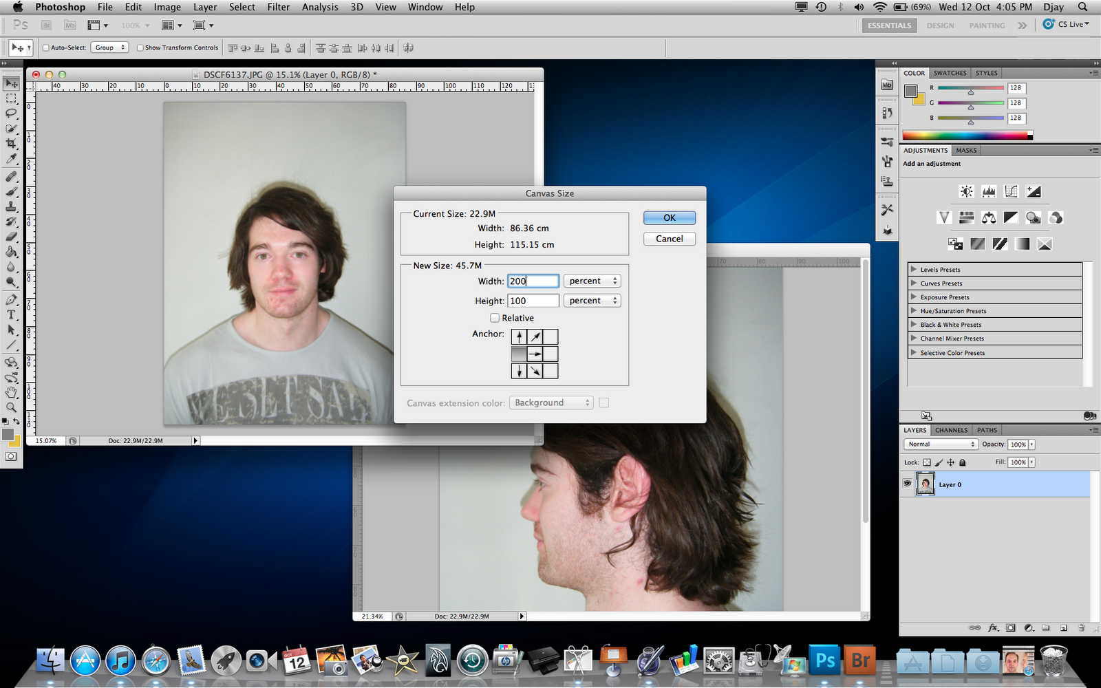
Create - shapes - spline - line -initial type corner - drag type corner

Aim is to draw each four sided polygon individually then to attach together into a mesh
Each four sided shape is required to be draw despite overlay
To aid in attachment the overlays need to be as close together as possible
Its possible to have these overlays assigned to the same points
hotkey a = snap tool (automatically moves cursor to specified selections when cursor is moved within close proximity (proximity can be adjusted))
Right click on snap icon (on top icon bar)
Deselect (if selected) grid
highlight vertex

Draw around first quad. Clicking in each corner.
When reaching final corner when asked to close spline click ok
Begin drawing around adjacent quad
When passing over previous vertices snap will allow you to place new vertex in same position
If proximity requires adjusting right click snap icon - options - adjust accordingly

Draw quads for all guideline quads

Select a single quad
Right click on line in modifier stack
Select convert to editable poly

Click on every quad
All quads are now attach to each other as a single entity of many parts
(picture shows mid process)

Select vertex mode
Drag select over all vertices
Since earlier vertices that would intersect were placed over each other the weld tools default settings will automatically only weld these vertices. Therefore no discriminate selection decisions are required
Select weld side box
Check settings and press ok
Now polygon mesh is all connected correctly ie all vertices are connected to vertices adjacent

This mesh follows contours of face are guided by reference plane front view
This 2D mesh now needs to be manipulated in 3rd dimension
Personal config change
View (top menu) - viewport configuration - changed layout too 2 screens
hotkey = Alt + x makes selected object see through
In vertex mode begin to drag and align verticies to side veiw reference picture
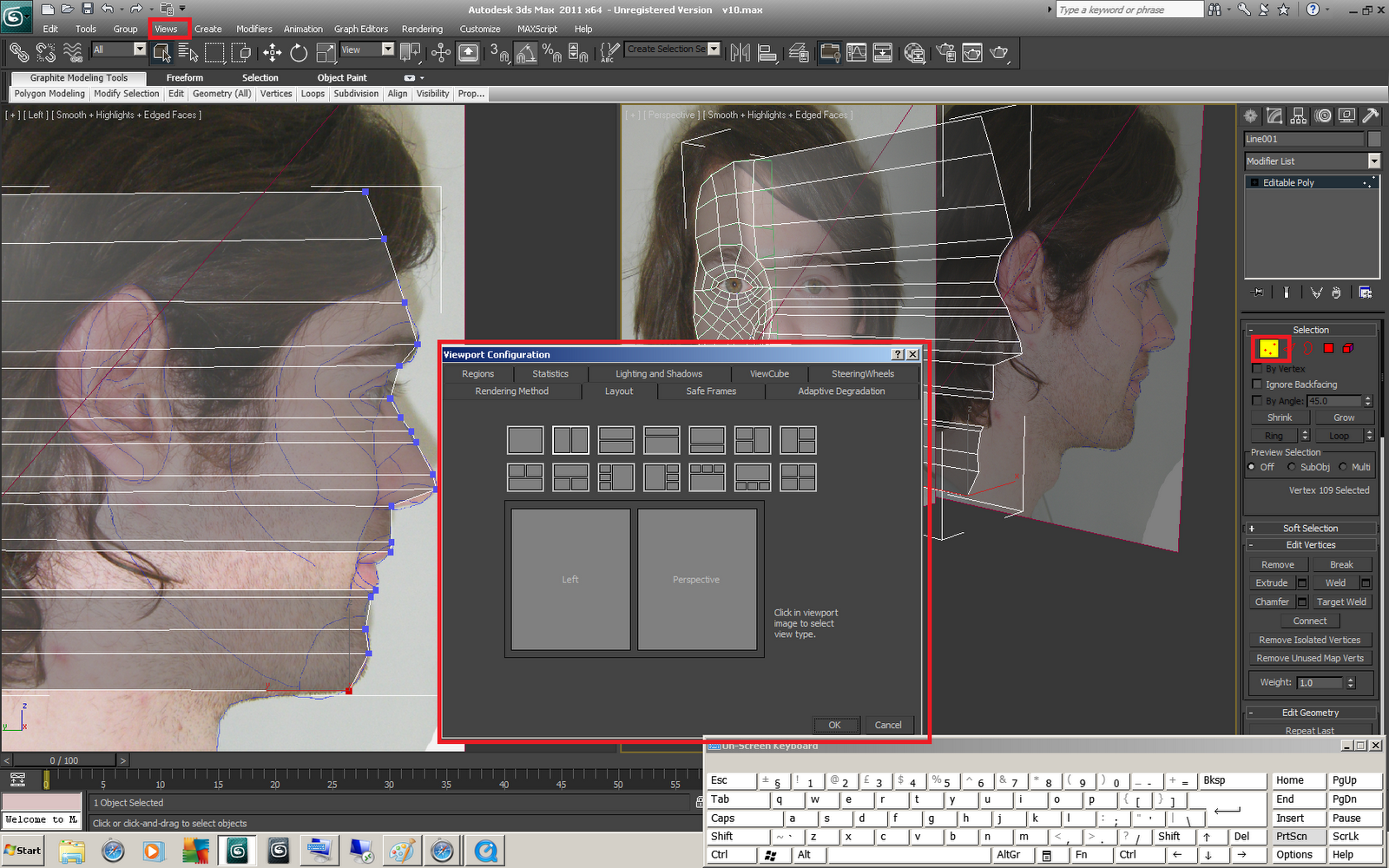
Continue process till all vertices are aligned in 3 dimensions

Above modifier stack select drop down box
select symmetry modifier
In modifier stack select symmetry "+"box to access mirror icon
if necessary select flip to position geometry on correct side

Using weld seem - slice along mirror - thershold - and the mirror tool itself position newly generated side of face next to original geometry slightly intersecting along "seem" effectively joining the two half as a single object

Add turbosmooth modifier from modifier list to increase geometry detail breaking single quads into smaller and smaller sections effectively smoothing the transition between polygons. This will allow or more realistic looking face

to adjust the geometry can be made by moving back down the modifier stack
The model will revert to its state before the next modifier (above selection in the stack)
adjustments can be made whilst looking at all modifiers activated (smooth and symmetry etc) by changing the icon (highlighted icon below the modifier stack) to show final result
This can be turned on and off as required
Each modifier can be turned on and off individually by turning the bulb next to each modifier on and off

NOSE
Nose quality involved extra geometry
This example involved this extra geometry being added
Geometry added using "cut" tool
Vertex mode - cut - position cursor over edge to cut - left click - move to any other edge / vertex as required to finish single cut - left click - move to another point to cut agin - right click to end

This geometries position was then adjusted using final result showing turbosmooth and symmetry to aid in creating a realistic nose shape with new geometry. Reference planes were refered to afterwards to adjust and align with pictures

Nostril creation involved adding extra geometry. The following geometry was created by using the inset tool. Using polygon selection - select polygons - select inset (box next too) - choose size of inset - select ok


(Extra lines of geometry being showed are due to glitch in configuring driver settings in 3ds max 2011 on home cpu. In polygon mode geometry is shown in triangles despite being set differently)
Newly created geometry via inset will now be used to create nostril cavity
Polygon mode - highlight newly inset geometry - extrude (box next to extrude - select depth - click ok
negative numbers reverse direction
Use scale move and rotate cursor options to manipulate extruded geometry as required

Nasil cavity shape was then adjusted using turbomooth and symmetry via final result tool. reference planes were not used as no viable reference could be used for required geometry

MOUTH
To crate mouth first adpated facial geometry to make create equal amount of geometry for top and bottom of mouth
Extra geometry added accordingly
(geometry are numbered as guide)

To connect gap used bridge tool
Edge mode - bridge tool box - check settings (simple to cover across two edge gap) - click ok
Repeat for each gap (attempting to accomplish this process in one motion ie not section by section my lead to complications ie twisting)
(example shows the 3 parts bridged and one part being bridged with tool (edges are highlighted red)

Add 2 lines of geometry using cut tool. lines made straight by slecting start and end points only. Cut tool automatically cuts through each edge of geometry

Patrude geometry to allow for easy visulisation of mouth

Align geometry with reference planes to create outer lips

Create new geometry using cut as before. This will be used to create the inner mouth

Move geometry to align with reference plate to create mouth

By following guide will create picture on left
This layout involves bad modelling geometry (Mis shapen quads and polygons of more/less sides of geometry)
8 lines of geometry all converging into a point
Upon smoothing undesirable results such as pinching will occur
Geometry was removed and added to produce picture on right to produce flowing geometry
Geometry was then reworked to flow with reference plane pictures